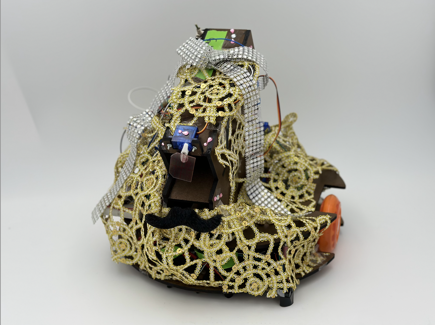
ROBOscars Robot
-
Objective
Your autonomous robot has been nominated for an award at the ROBOscars. The objective is to deliver more good press to your audience than your opponent does to theirs, and/or deliver sufficient bad press to your opponent’s audience to offset their ratings. Good press is worth 3 points and bad press removes 2 points off of the other team's score. The robot with the highest score at the end of 2 minutes and 10 seconds of gameplay wins!
-
Outcome
While there were many strategies to achieve this objective, we decided that we wanted our robot to work as consistently as possible. To us this meant following the line and dumping balls straight into the bucket (as opposed to a more risky approach such as launching projectiles). With beauty and brains, our robot stole the red carpet and won 1st place at the ROBOscars against 20 other student teams!
The Game
Your robot will start in its respective Studio at a randomized orientation where you can manually load up to 4x press (represented by balls). You may also engage with your robot only while it is in the Studio via a switch, button, or potentiometer. The playing field has a red carpet leading to the press scales. Additionally, IR beacons are placed in each STUDIO, emitting at a height of 7 inches with a frequency of 3333 Hz for Film A and a frequency of 909 Hz for Film B. Black tape is placed between each half of the playing field and the scales while a wall lines the perimeter of the remaining 3 walls.
Design Choices
Chassis and Drivetrain:
Two driving wheels centered on the robot for a tight turning radius.
Two castors for stability.
Motors mounted in line with drive wheels through shaft couplers.
Two 7.2V batteries connected in series with a voltage regulator to power motors at 12V.
Studio:
One shielded IR sensor to sense the beacon at 7in. up from the ground. Works for both beacon frequencies.
One switch to indicate if the robot should go to the good or bad press bucket.
One button to indicate that the balls had been loaded and the robot was safe to drive out of the studio.
Line Following:
Three closely positioned shielded phototransistor to follow the red line.
One outrigger phototransistor to sense Bad Press fork.
Delivery of Press:
Four balls sit in an angled chute blocked by a gate.
Small independently powered servo opens the gate to release balls.
Mechanical Design
Chassis Subsystem
Ball Drop Subsystem
Beacon Sensing Subassembly
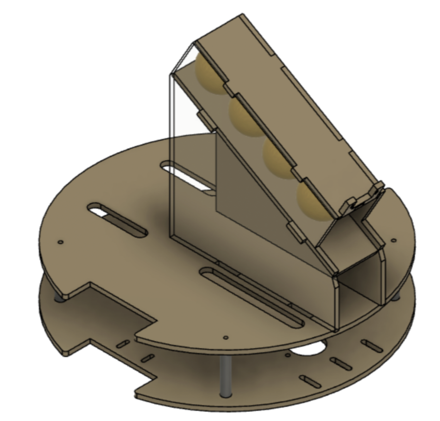
The chassis has two layers connected by 4 aluminum standoffs. Four cable passthroughs on the top surface allow wires to run freely between the two layers. The initial chassis prototype was square, but the shape was changed to a circle so that the sharp corners could not get stuck in the corners of the field.
The robot moves using two driven wheels on the sides of the chassis and two omnidirectional casters on the front and back. Since the wheels are tangent to the chassis and centered front to back, the robot can spin in place. This was important for our system, since it allowed the robot to easily complete the sharp turns along the red carpet without the center of the robot straying too far from the line.
The 4 balls are loaded into an inclined (30°) chute on top of the robot, which keeps them secure while the robot traverses the course. The balls are held on the ramp with a plastic gate connected to a 180° servo motor. Once the robot has arrived at the intended goal, the servo is actuated and the balls roll out of the chute into the goal.
The ball delivery subsystem was constructed out of laser cut duron panels with tabs for alignment. The panels were joined using CA glue. The subsystem was fixed to the chassis using a friction fit and electrical tape, which allowed the whole system to be recut and switched out if any modifications needed to be made during testing.
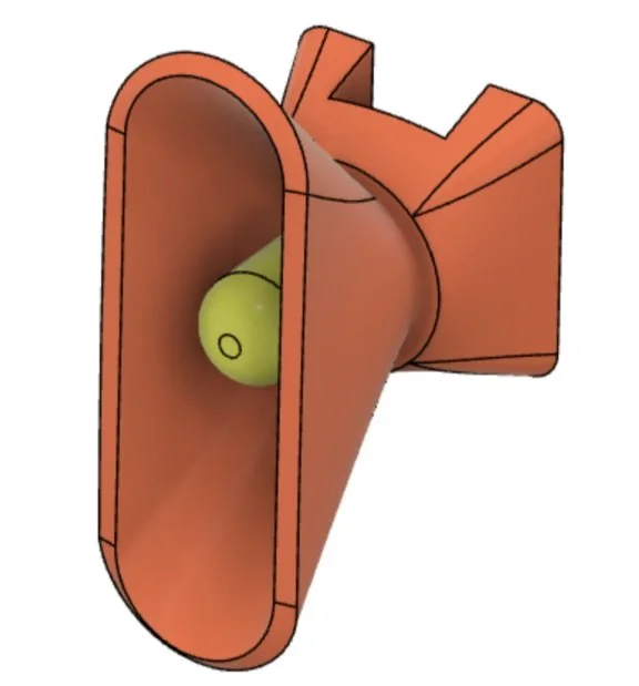
To improve the resolution of our orientating method, the beacon sensing phototransistor was placed into a narrow cone to limit its field of view to approximately 30 degrees horizontally. This was intended to reduce the likelihood that the signal would spike too early, before the phototransistor aligned with the beacon. This seemed to work well as the robot consistently oriented properly and never actuated too early.
Electrical Design
Power
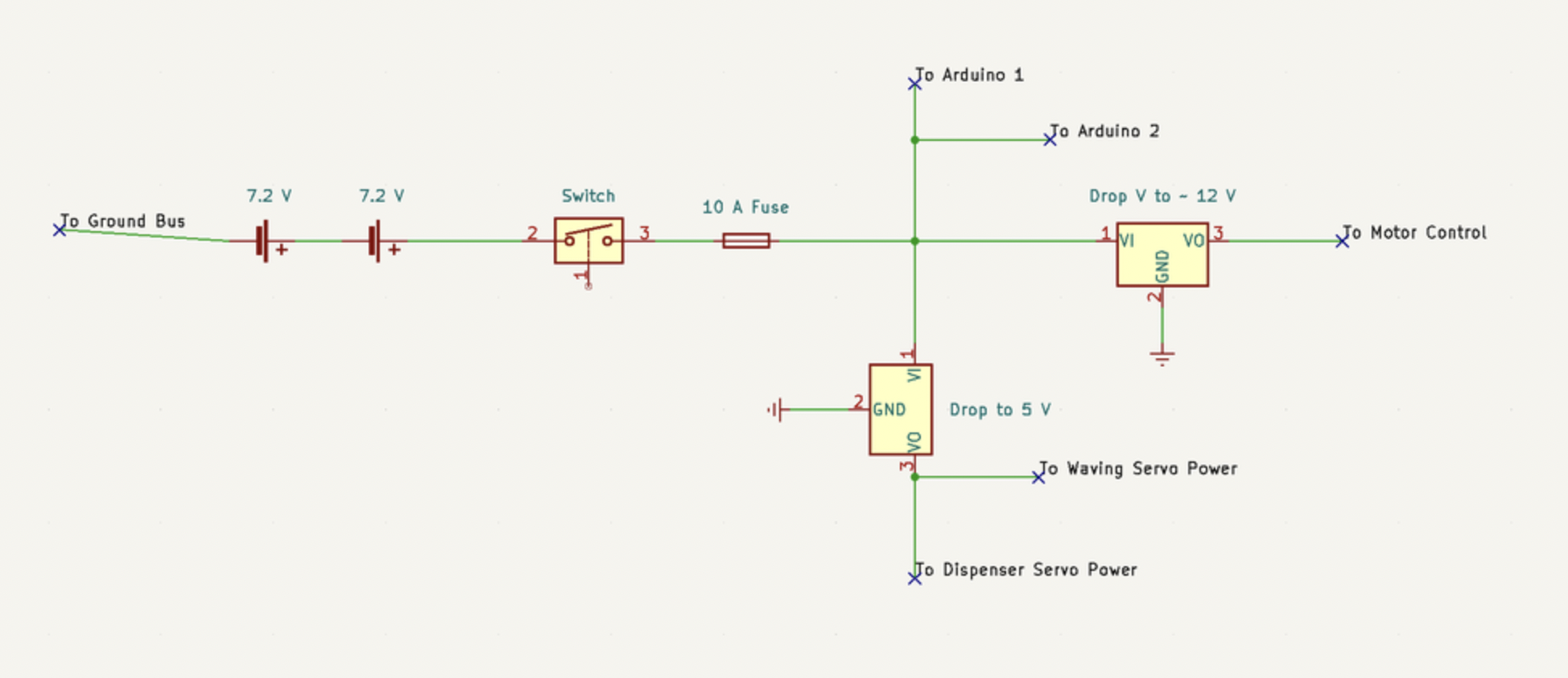
We have our two 7.2V NiMH batteries wired in series to get high enough voltage to drive the 12V motors. The batteries then run through a switch that acts as an e-stop. After the switch we have a 10A fuse to prevent battery overheating in the event of a stall or more likely a short circuit. We then send the battery voltage to power the two Arduinos (their Vin pin accepts 6 - 20V and has a built in voltage regulator). To drive the motors, we want consistent voltage to mitigate performance variations as the batteries drain. A voltage regulator that dropped the ~16.2V peak battery voltage down to closer to 12V accomplishes this. The servos, as it turns out, can not be driven off an Arduino. The 0.5A peak current drawn by the servo strains the Arduino's power system and messes up the logic. To fix this problem we installed a 5V regulator to bring down the battery voltage and drove the servo off of that supply. We wired the battery ground to a bus and then into the ground rail of our main breadboard. This served as our common ground for the circuits and eliminated the potential for floating ground issues. To facilitate easy battery swaps and charging, we soldered the battery leads to connectors that we could unplug conveniently.
Line Following
Because line following was so integral to our strategy, we wanted to make a robust circuit that would be reliable and consistent. This meant filtering out noise and sunlight so that our thresholds would remain constant irrespective of conditions or the time of the day. In order to preserve the input signal from the emitter into the detector, we pulsed the LED at a frequency of 500 Hz.
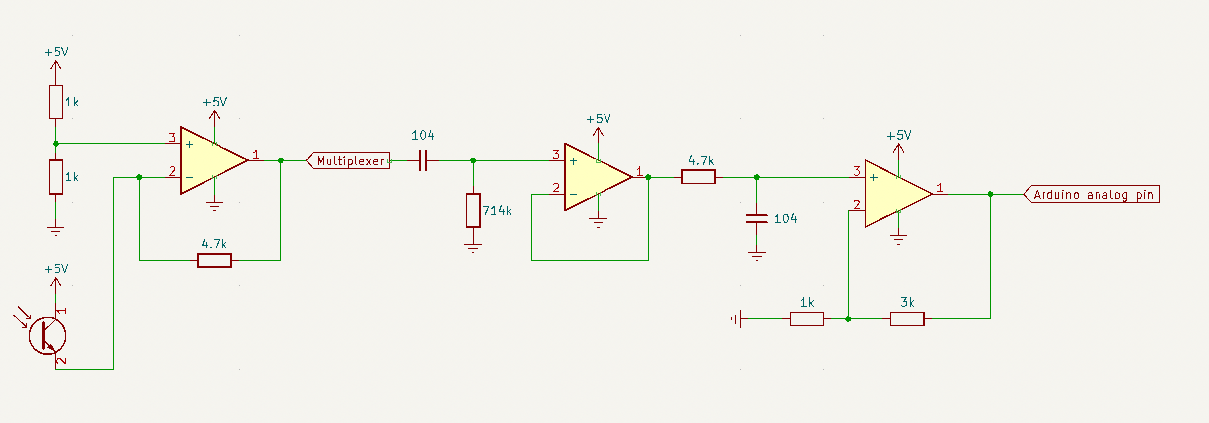
Stage 1: Trans-Resistive circuit to allow for linear readings from the phototransistors.
Stage 2: Multiplexer to allow for one output for all four sensors in an effort to save Arduino pins and complexity of bread board.
Stage 3: High pass filter with corner frequency of approximately 2 Hz to remove the DC offset from sunlight and decouple the dependence on lighting conditions of the room.
Stage 4: Unity gain buffer to isolate the stages.
Stage 5: Low pass filter with corner frequency of approximately 340 Hz to flatten out the signals and allow us to directly read the analog value as the threshold.
Stage 6: Gain of four to increase the resolution between line thresholds and minimize potential for error.
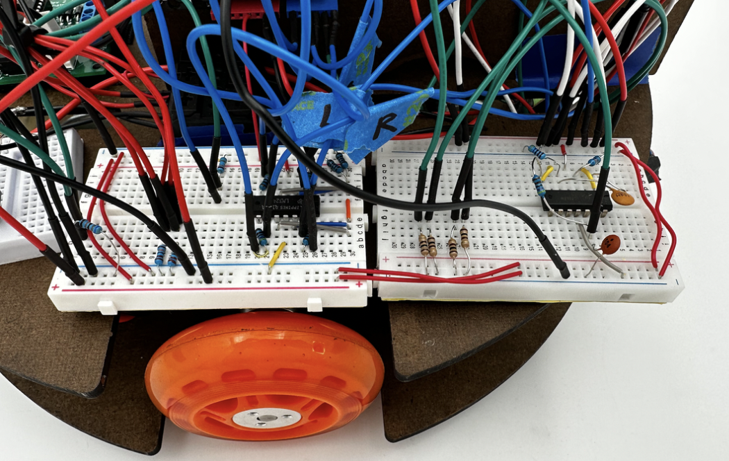
For our line following sensors, we originally designed a multi-stage circuit that we passed through a multiplexer to allow the output of the phototransistors to all share the same stages of the rest of the circuit. We felt that this would save Arduino pins while also limiting the potential for error in duplicating four of these complex circuits. The pin out and the logic for the channels are shown below and we were able to get the circuit working reliably.
However, we encountered issues with the multiplexer's ability to process the signals at a fast enough rate to execute effective line following. Because the input into the multiplexer was. a waveform, we needed to allow it to stabilize before switching to other channels in order to get an accurate reading. While this only took milliseconds to read, this was enough time for the robot to get off track while the multiplexer had to cycle through all the channels.
After sinking many hours trying to get the multiplexer to work, we ultimately decided to cut our losses and only use the first stage of the original circuit, the trans-resistive circuit. We were able to achieve good enough resolution for our thresholds with only this one stage and we no longer had to pulse our LEDs. We also added shields to filter out the sunlight in an attempt to keep our thresholds constant no matter the conditions. While not as robust as our original signal processing circuit, this worked reliably in all lighting settings that we tested under. The schematic and picture of this circuit is shown below.
Beacon Sensing
The first stage of the beacon sensing circuit was a high pass filter with a corner frequency of 34 Hz. This was designed to eliminate any noise while allowing both beacons of 999Hz and 3333Hz to pass through. Then a low pass filter with a corner frequency of 3386 Hz was used. The low pass served to flatten the signal because of the RC time constant which made it intelligible to the analog pin. It’s ok that the 3300 Hz beacon has its signal attenuated slightly. We were comfortably able to set a threshold that would read either beacon when it was close, and not read the far beacon. The decay of the signal with distance is far more significant than attenuation from the low pass.
Software Design
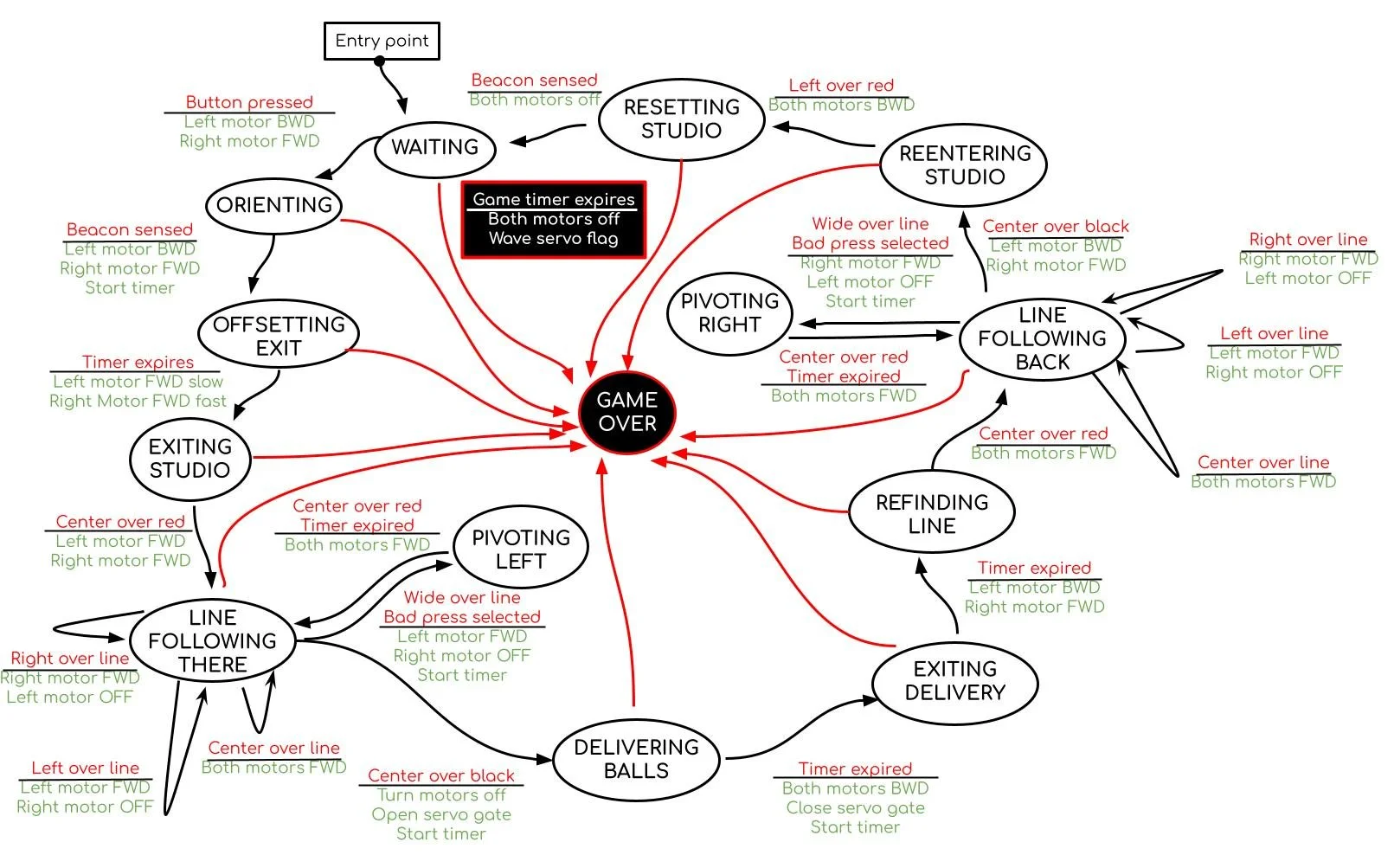
State Diagram
Pseudo Code
If button is pressed, spin in place.
If the beacon is sensed, turn left in place slightly and then move forward while arcing to the right.
If the line is hit, begin line following (If left sensor is hit, turn left. If right sensor is hit, turn right. If center sensor is hit, drive forward).
If it reaches the branch and bad press is selected, pivot left until the line is sensed again and then resume line following.
If the black line is sensed, open the servo gate to drop the balls.
If the gate has been open for half a second, close the gate, drive backwards for half a second, and turn in place.
If the center sensor senses red, begin line following.
If it reaches the branch and bad press is selected, pivot right until the line is sensed again and then resume line following.
If the black line is detected, turn in place.
If the red line is detected, drive backward.
If the beacon is sensed, turn motors off, wait for button press, and begin this loop again.
If at any point two minutes and ten seconds elapses, turn motors off and end game.
-
#include <Arduino.h>
#include <Servo.h>
Servo myservo;
#define MOT_LEFT 5
#define MOT_RIGHT 6 //goes to E2 on motor driver
#define MOT_LEFT_DIR 7
#define MOT_RIGHT_DIR 8
#define SERVO 13
#define PRESS_OPT 12
#define START_BUTTON 11
#define TAPE_RIGHT A5
#define TAPE_CENTER A0
#define TAPE_LEFT A2
#define TAPE_OUTRIGGER A3
#define BEACON A4
#define MAX_SPEED 255
#define MIN_SPEED 230
#define RED_LINE_THRESH_RIGHT 250
#define RED_LINE_THRESH_CENTER 220
#define RED_LINE_THRESH_LEFT 250
#define RED_LINE_THRESH_WIDE 250
#define BLACK_LINE_THRESH 400
#define L_MOT_FWD false
#define L_MOT_BWD true
#define R_MOT_FWD true
#define R_MOT_BWD false
#define GATE_OPENED 100
#define GATE_CLOSED 0
#define SERVO_INT 500 //ms
#define ORIENT_INT 200 //ms
#define BEACON_VAL 100
#define END_TIME 130000
//function prototypes
void driveForward();
void driveBackward();
void turnLeftInPlace();
void turnRightInPlace();
void turnRightGradually();
void turnMotorsOff();
bool leftOverLine();
bool centerOverLine();
bool rightOverLine();
bool wideOverLine();
bool centerOverBlack();
bool centerOverRed();
bool leftOverRed();
bool rightOverRed();
bool beaconSensed();
bool goodPressSelected();
bool badPressSelected();
bool buttonPressed();
void pivotLeft();
void pivotRight();
void turnLeft();
void turnRight();
//state definitions
typedef enum {
STATE_LINE_FOLLOW_THERE, STATE_LINE_FOLLOW_BACK, STATE_GAMEOVER, STATE_ORIENT, STATE_WAITING,
STATE_EXIT_STUDIO, STATE_REFIND_LINE, STATE_REENTER_STUDIO, STATE_RESET_STUDIO,
STATE_PIVOT_LEFT, STATE_PIVOT_RIGHT, STATE_OFFSET_EXIT, STATE_BALL_DELIVERY, STATE_EXIT_DELIVERY
} States_t;
//module variables
States_t state;
unsigned long startTime;
unsigned long gameTime;
unsigned long currentTime;
void setup() {
// put your setup code here, to run once:
Serial.begin(9600);
while(!Serial);
pinMode(MOT_LEFT, OUTPUT);
pinMode(MOT_RIGHT, OUTPUT);
pinMode(TAPE_LEFT, INPUT);
pinMode(TAPE_CENTER, INPUT);
pinMode(TAPE_RIGHT, INPUT);
pinMode(TAPE_OUTRIGGER, INPUT);
pinMode(BEACON, INPUT);
pinMode(PRESS_OPT, INPUT);
pinMode(START_BUTTON, INPUT);
myservo.attach(SERVO);
myservo.write(GATE_CLOSED);
state = STATE_WAITING;
gameTime = millis();
}
void loop() {
//put your main code here, to run repeatedly:
currentTime = millis();
if(currentTime - gameTime >= END_TIME) {
turnMotorsOff();
state = STATE_GAMEOVER;
}
switch (state) {
case STATE_WAITING:
if(buttonPressed()){
turnLeftInPlace();
state = STATE_ORIENT;
}
break;
case STATE_ORIENT:
if(beaconSensed()) {
turnLeftInPlace();
startTime = millis();
state = STATE_OFFSET_EXIT;
}
break;
case STATE_OFFSET_EXIT:
if (millis() > startTime + 300) {
turnRightGradually();
startTime = millis();
state = STATE_EXIT_STUDIO;
}
break;
case STATE_EXIT_STUDIO:
if(centerOverRed() && (millis() > startTime + 1000)){
state = STATE_LINE_FOLLOW_THERE;
}
break;
case STATE_LINE_FOLLOW_THERE:
if(wideOverLine() && badPressSelected()) {
pivotLeft();
startTime = millis();
state = STATE_PIVOT_LEFT;
}
else if(centerOverLine()) driveForward();
else if(rightOverLine())pivotRight();
else if(leftOverLine()) pivotLeft();
if(centerOverBlack()) {
turnMotorsOff();
myservo.write(GATE_OPENED);
startTime = millis();
state = STATE_BALL_DELIVERY;
}
break;
case STATE_BALL_DELIVERY:
if(millis() > startTime + 500) {
driveBackward();
startTime = millis();
myservo.write(GATE_CLOSED);
state = STATE_EXIT_DELIVERY;
}
break;
case STATE_EXIT_DELIVERY:
if(millis() > startTime + 500) {
turnLeftInPlace();
startTime = millis();
state = STATE_REFIND_LINE;
}
break;
case STATE_PIVOT_LEFT:
if(centerOverLine() && (millis() > startTime + 600)) {
state = STATE_LINE_FOLLOW_THERE;
}
break;
case STATE_PIVOT_RIGHT:
if(centerOverLine() && (millis() > startTime + 600)) {
state = STATE_LINE_FOLLOW_BACK;
}
break;
case STATE_REFIND_LINE:
if(centerOverRed() && (millis() > startTime+1000)) {
driveForward();
state = STATE_LINE_FOLLOW_BACK;
}
break;
case STATE_LINE_FOLLOW_BACK:
if(wideOverLine() && badPressSelected()) {
pivotRight();
startTime = millis();
state = STATE_PIVOT_RIGHT;
}
else if(centerOverLine()) driveForward();
else if(rightOverLine())pivotRight();
else if(leftOverLine()) pivotLeft();
if(centerOverBlack()) {
turnLeftInPlace();
startTime = millis();
state = STATE_REENTER_STUDIO;
}
break;
case STATE_REENTER_STUDIO:
if(leftOverRed() && (millis() > startTime + 500)) {
driveBackward();
state = STATE_RESET_STUDIO;
}
break;
case STATE_RESET_STUDIO:
if(beaconSensed()) {
turnMotorsOff();
state=STATE_WAITING;
}
break;
case STATE_GAMEOVER:
break;
default: //should never get to this unhandled state
Serial.println("something is seriously wrong :(");
}
}
void driveForward() {
analogWrite(MOT_LEFT, MIN_SPEED);
digitalWrite(MOT_LEFT_DIR, L_MOT_FWD);
analogWrite(MOT_RIGHT, MIN_SPEED);
digitalWrite(MOT_RIGHT_DIR, R_MOT_FWD);
}
void driveBackward() {
analogWrite(MOT_LEFT, MIN_SPEED);
digitalWrite(MOT_LEFT_DIR, L_MOT_BWD);
analogWrite(MOT_RIGHT, MIN_SPEED);
digitalWrite(MOT_RIGHT_DIR, R_MOT_BWD);
}
void turnLeftInPlace() {
analogWrite(MOT_LEFT, MIN_SPEED);
digitalWrite(MOT_LEFT_DIR, L_MOT_BWD);
analogWrite(MOT_RIGHT, MIN_SPEED);
digitalWrite(MOT_RIGHT_DIR, R_MOT_FWD);
}
void pivotLeft() {
analogWrite(MOT_LEFT, MIN_SPEED);
digitalWrite(MOT_LEFT_DIR, L_MOT_FWD);
analogWrite(MOT_RIGHT, 0);
digitalWrite(MOT_RIGHT_DIR, R_MOT_FWD);
}
void pivotRight() {
analogWrite(MOT_LEFT, 0);
digitalWrite(MOT_LEFT_DIR, L_MOT_FWD);
analogWrite(MOT_RIGHT, MIN_SPEED);
digitalWrite(MOT_RIGHT_DIR, R_MOT_FWD);
}
void turnRightInPlace() {
analogWrite(MOT_LEFT, MIN_SPEED);
digitalWrite(MOT_LEFT_DIR, L_MOT_FWD);
analogWrite(MOT_RIGHT, MIN_SPEED);
digitalWrite(MOT_RIGHT_DIR, R_MOT_BWD);
}
void turnRightGradually() {
analogWrite(MOT_LEFT, 100);
digitalWrite(MOT_LEFT_DIR, L_MOT_FWD);
analogWrite(MOT_RIGHT, 255);
digitalWrite(MOT_RIGHT_DIR, R_MOT_FWD);
}
void turnMotorsOff() {
digitalWrite(MOT_LEFT, LOW);
digitalWrite(MOT_RIGHT, LOW);
}
bool leftOverLine() {
return(analogRead(TAPE_LEFT) > RED_LINE_THRESH_LEFT);
}
bool centerOverLine() {
return(analogRead(TAPE_CENTER) > RED_LINE_THRESH_CENTER);
}
bool rightOverLine() {
return(analogRead(TAPE_RIGHT) > RED_LINE_THRESH_RIGHT);
}
bool wideOverLine() {
return(analogRead(TAPE_OUTRIGGER) > RED_LINE_THRESH_WIDE);
}
bool centerOverBlack() {
return(analogRead(TAPE_CENTER) > BLACK_LINE_THRESH);
}
bool rightOverBlack() {
return(analogRead(TAPE_RIGHT) > BLACK_LINE_THRESH);
}
bool leftOverBlack() {
return(analogRead(TAPE_LEFT) > BLACK_LINE_THRESH);
}
bool centerOverRed(){
return(analogRead(TAPE_CENTER) < BLACK_LINE_THRESH && analogRead(TAPE_CENTER) > RED_LINE_THRESH_CENTER);
}
bool leftOverRed(){
return(analogRead(TAPE_LEFT) < BLACK_LINE_THRESH && analogRead(TAPE_LEFT) > RED_LINE_THRESH_LEFT);
}
bool rightOverRed(){
return(analogRead(TAPE_RIGHT) < BLACK_LINE_THRESH && analogRead(TAPE_RIGHT) > RED_LINE_THRESH_RIGHT);
}
bool beaconSensed() {
return(analogRead(BEACON) > BEACON_VAL);
}
bool goodPressSelected() {
return(digitalRead(PRESS_OPT) == HIGH);
}
bool badPressSelected() {
return(digitalRead(PRESS_OPT) == LOW);
}
bool buttonPressed() {
return(digitalRead(START_BUTTON) == HIGH);
}
Functionality Video
Our robot is able to go to either of the press buckets! We are able to control this through a switch that indicates where we want the robot to go, either to good press or to bad press. You can see me in this video controlling this while the robot is in the studio as well as pushing the button to indicate to the robot that it can begin leaving the studio.
