Metal 3D Printed Heat Exchanger
-
Objective
Design a heat exchanger with a shape complicated enough to justify the use of LPBF. It must be contained within a 80x80x80mm bounding box and printed as one part. There can be absolutely no mixing of fluids. The hot water will come in around 80C and the cold around 15C. The heat exchanger must cool the hot flow by at least 20C.
-
Outcome
We ultimately went with a gyroid lattice heat exchanger as it is complex enough to justify 3D printing while also being easily printable due to its ability to self support. This lattice also has a great surface area to volume ratio and induces turbulence into the flow which helps with heat transfer. Our heat exchanger saw a max temperature decrease of 30C, exceeding the requirement.
Design Concept
In order to guide our ideation, we decided on four key criteria for our heat exchanger.
Justification of metal AM
Printability
Surface area
Turbulence
For us, the intuitive decision was to move forward with a lattice as they have great surface area to volume ratios and are well suited to additive manufacturing. We ultimately landed on a gyroid lattice due to its self supporting geometry, which is crucial to printing without internal supports. Additionally, this geometry induces turbulence in the flow, which further increases heat transfer. The geometry also naturally creates two congruent passages, which is ideal for keeping the two fluids separate.
nTopology
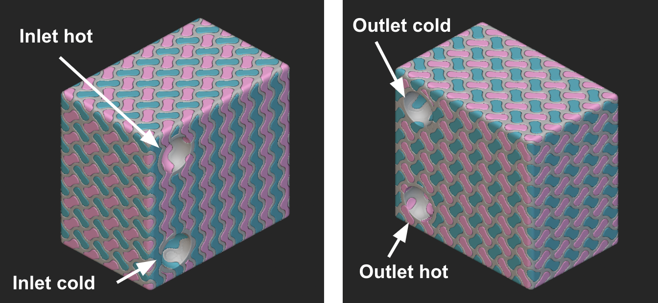
In order to best design such a device, we wanted to utilize nTopology, a software with strong latticing capabilities. We designed a heat exchanger using the Rectangular Volume Lattice tool with a rectangular form factor, with 2 inlets and 2 outlets. The design space was delineated by the internal geometry of the heat exchanger form factor, with semi-circular cutouts made at each inlet and outlet. By creating these semi-circular cutouts, we increased the number of potential pathways for the fluid to travel both in and out, thus decreasing the pressure drop.
In this model, we chose an 8x8x8mm unit cell size with a 1.5mm wall thickness. The 8mm3 unit cell size was the smallest cell size we felt was reasonable given the overall dimensions. By minimizing the size of the unit cell, we drastically increased the surface area to 91,733mm2. Although decreasing the wall thickness would further increase the heat transfer, we chose to use the 1.5mm thickness to decrease the risk of porosity in the walls that could lead to liquid mixing, the most important design criteria to be met.
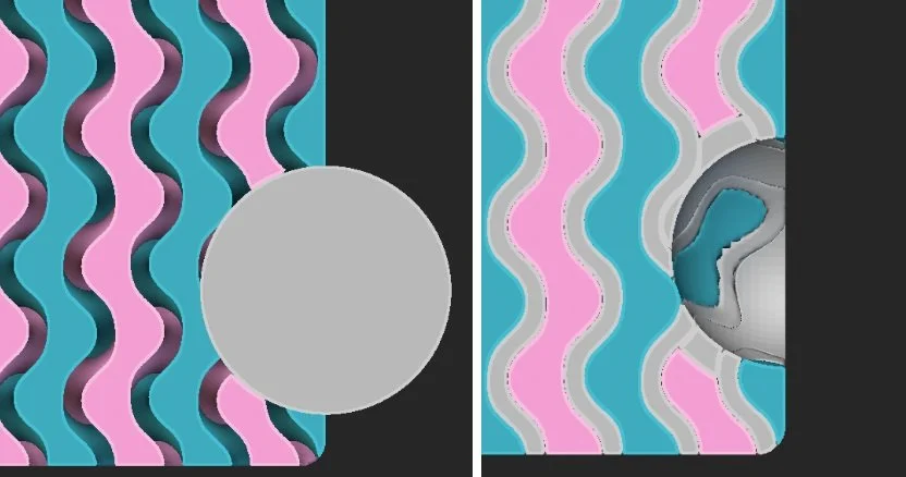
It was challenging but fun to learn a new modeling software and we struggled a bit in the beginning with how to make sure we separated the two fluids at the inlets and outlets. Eventually, we figured out how to make the baffle geometry. The purpose of the baffles is to restrict flow to only one fluid at each location. To do so, we modeled a sphere centered at the semi-spherical indentation in the lattice, and oversized it by 1.5mm. Next, we used a boolean intersect tool between one of the liquids and the sphere. For example, for the cold inlet, we want to allow only cold liquid to enter, and thus need to “plug” the ends of the hot liquid. A boolean intersection operation between the hot liquid and the sphere results in a new body that blocks only the hot liquid. This baffle creation operation was done at all inlets and outlets, and then merged with the lattice.
Determining the design of these baffles plays a large role in the final fluid flow. We designed the inlets and outlets of each liquid to be diagonal from each other. This increased the length of travel of the fluids, and thus the time when the fluids are indirectly interacting and transferring heat.
Printing (or trying to…)
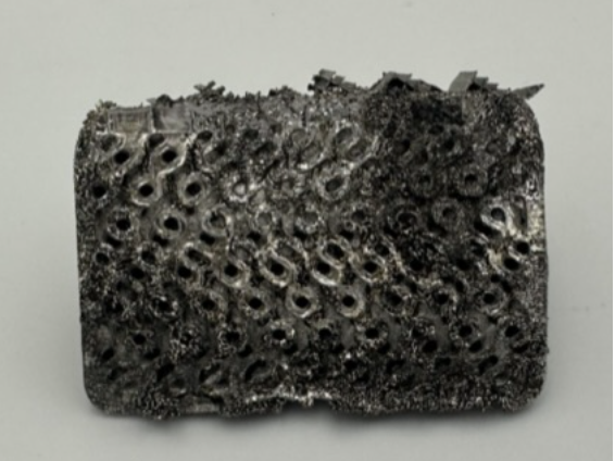
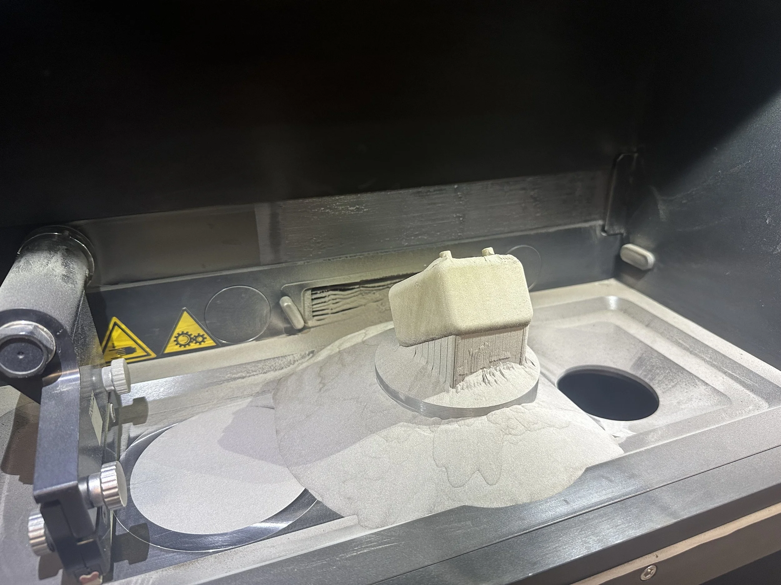
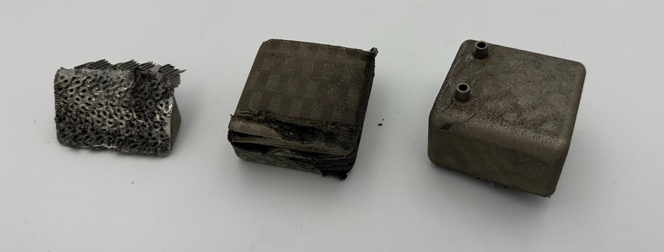
While the design constraint is technically an 80mm cube, there is a limitation on the height of the print on the Trumpf printer of roughly 65mm due to the volume of powder that can be in the supplier and our desired oversupply factor of 200%. Knowing this, our first iteration of our heat exchanger had a total size of 80x80x54mm. This allowed us to be comfortably under the 65mm height constraint while also leaving some extra room for the supports required for attachment to the build plate. While this geometry and size can technically be printed on the Trumpf, it did not allow for significant rotation in the slicer. This is important because ideally you want to minimize the surface area of each layer to minimize heat that can lead to warping. Unfortunately, the inability to rotate the print significantly did ultimately lead to a failed print due to significant warping. In fact, the layers became so uneven that the recoater was broken during the print. This prevented future layers of powder from being redistributed across the part so the print was unable to complete. As you can see in the image below on the left, the gyroidal lattice is very dense which makes sense why there was significant distortion.
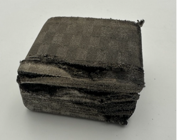
For the second print, we used the same file but scaled down the overall size so as to allow for more rotation of the part in relation to the print bed. The idea was to decrease the cross sectional area for a given layer to minimize warpage. While this second print made it further than the first, it also warped significantly and did not complete as shown below on the right.
Model Updates to Limit Warpage
After two failed attempts, we realized that we needed to alter our geometry to increase the part’s printability.
Unit cell size increased from 8mm to 20mm to decrease scanning area. Initially, we were hesitant to do this because of the importance of surface area in heat transfer. While theoretically the unit cell size should be as small as possible, there is a practical limit due to the tradeoff between printability and surface area maximization.
Wall thickness decreased from 1.5mm to 1mm to decrease scanning area and increase heat transfer.
Shell size decreased from 80x80x54mm to 60x60x54mm to allow for more for more rotation during slicing and thus decreased scanning area while also ensuring that the supplier could provide enough powder to the part.
Some back of the envelope calculations confirmed that the reduction in surface area from 91,733mm2 to 39, 698mm2 would still allow us to meet the required temperature drop of 20C so we proceeded with this updated design.
Printing Success!
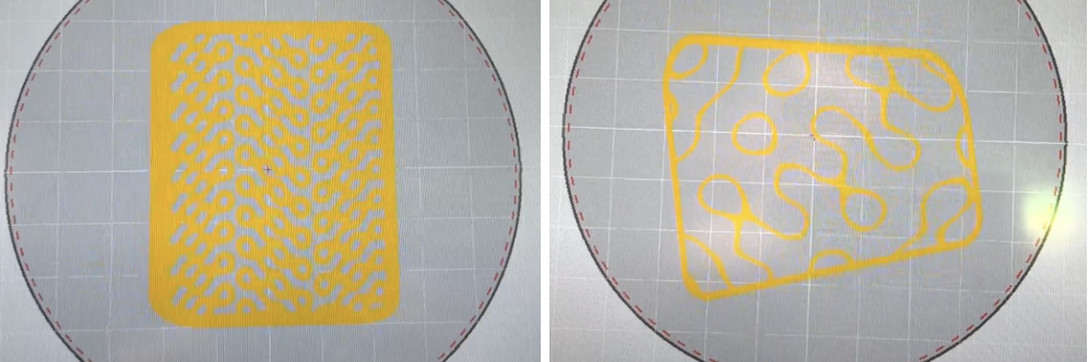
Once we had confirmed the new design would be in the right ballpark from a heat transfer perspective, we were ready to slice and print it. Due to the decreased overall size of the second design, we were also able to rotate the heat exchanger at a compound angle in both x and y to minimize the scanning surface area for a given layer. This resulted in a final z height of approximately 56 mm, significantly below the maximum height of 65mm. As illustrated below, the slicer shows our updated design (right) has far less scanning area than the original design (left) due to our design changes. We hoped this would significantly decrease the risk of warping during the print.
This print ended up being successful with no visible warping. There was only one small defect in the form of a hole on the outer surface of the heat exchanger, but this was easily patched up with some electrical tape. The final print parameters we used to ensure a good print were as follows:
Chess Scanning Pattern: 3x3x1mm chess pattern
Laser Power: 100W
Oversupply Percentage: 165%
Scan Velocity: 500mm/s
Recoater Layer Thickness: 60 um for first half of layers, 30um for second half
Through these three prints, we learned about how to weigh the tradeoffs between surface area, wall thickness, and overall size to determine printability. In each iteration, our prints progressively improved until we had a good final result as seen below.
Mixing Testing
First, mixing testing was conducted to ensure that the fluids in fact did not mix and that the internal gyroid structure was designed and printed properly. This was done using water with colored dye at one inlet and clear water at the other inlet. Our heat exchanger passed this test as the clear fluid was not contaminated with any dye at the outlet of the heat exchanger.
Cooling Testing
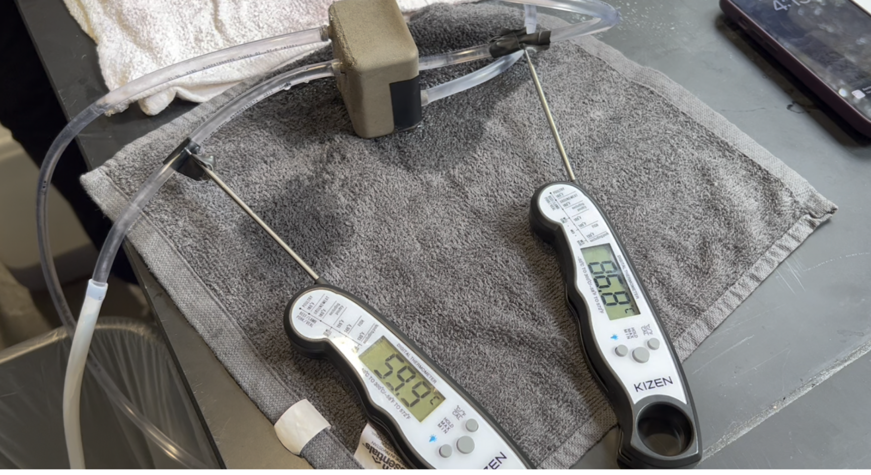
Once we knew no mixing occurred, we moved on to testing the heat transfer capabilities of our heat exchanger. The cooling test was conducted using boiled water (high of 86°C) on one inlet and cooled water (assumed to be 15°C) on the other inlet. We measured the temperature of the hot water inlet and hot water outlet in order to determine the ΔT of the heat exchanger. There were two tests conducted, parallel flow and counterflow.
With our parallel flow test, we were able to achieve a maximum temperature drop of 29.9°C, from an inlet temperature of 84.8°C to an outlet temperature of 54.9°C. To perform the counterflow test, we swapped the inlet of cold water with the cold water outlet of the original test and kept the probes on both the inlet and outlet of the hot water channel. To our surprise, the counterflow experiment provided worse results, with a peak temperature delta of 20.3°C, about a 32% decrease from the parallel flow. However, like with any testing setup, there were testing limitations that may have affected the results. First, we did not wait long after the parallel flow study before we conducted the parallel flow study. In fact, it was noticeably warmer than room temperature at the start of the counterflow test. This reduced the effectiveness of the exchanger as the temperature difference between the fluids and heat exchanger walls was reduced. Additionally, the structure of the test relied on human input of pressure onto a syringe and an attempt to generate the same flow rate between the two fluids. Flow rate is an important parameter in heat transfer so discrepancies between the hot and cold flow rates can significantly affect the observed temperature drop. Overall, despite these potential points of error, our heat exchanger met the 20°C temperature drop required for both the parallel and counterflow configurations.


